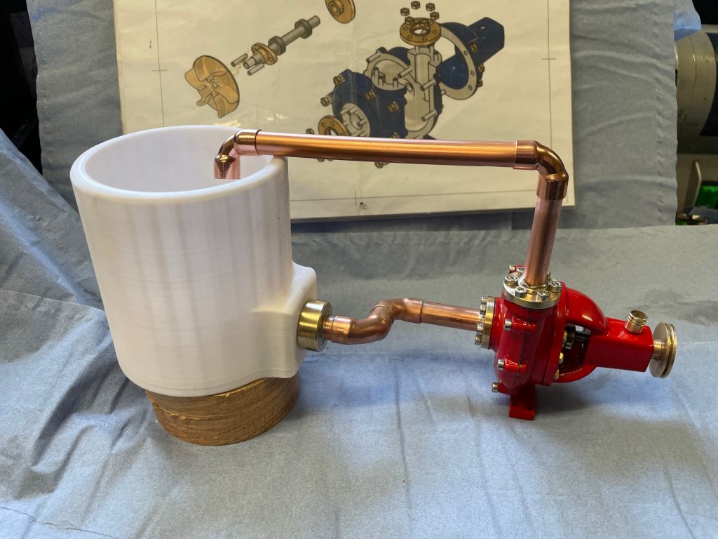
Cringle Engineering pump with 3D printed container.
Cringle pump with 3D printed container.
Background
Model Centrifugal pump kit from Cringle Engineering was a recent purchase that had peaked my interest as a model. Due to the fact that for most of my working life in the Fire Service, pumps were centre stage.
Finding such a kit with links to my past working life (but in a much smaller size of course) was just the sort of project needed, since the last few weeks of 2021 were spent in the wood workshop, making a river table.
Model Centrifugal Pump Kit as delivered.
Inspecting each casting I was pleased with the aluminium ones in both quality and finish, the brass/bronze ones didn’t quite come up to the standard and the impeller in particular will require a lot of work. But that’s the fun part(?!!!).
The kit contains-
-3 alloy castings
2 cast brass pipe flanges
1 cast brass gland
cast brass impeller
cast brass pulley
2 bearings
stainless steal shaft
stainless steel threaded rod
brass nuts
rubber o ring seal and
6 pages of technical drawings
I’ve been fairly busy in the metal workshop working on the ‘Cringle’ water pump. Whilst there have been a few ‘modifications’ it remains closely aligned to the pump as designed.
Cringle pump with 3D printed container.
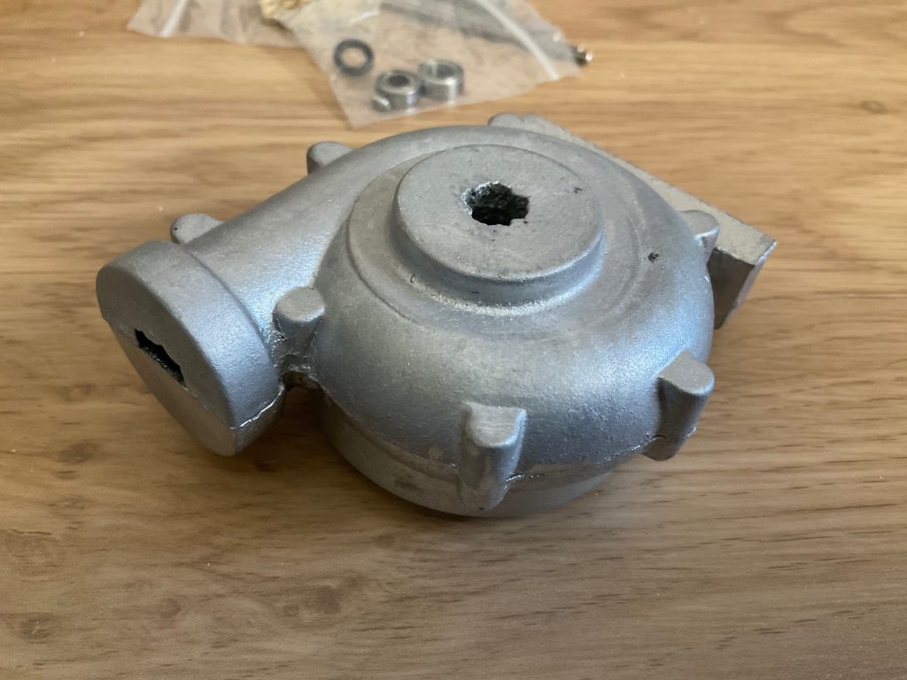
Bell Housing
Nice quality finish
The main pump body
Foot of the pump is just on one half
Cringle Engineering casting are very good quality
Inside the pump
|Pump casing requires little work
Pump casing half with foot.
Miscellaneous parts including 2 bearings and some nice brass nuts
Brass castings supplied with the Cringle Engineering pump kit
Cringle pump brass castings
The finished size of the pump itself are :-
Height – 82mm
Width – 70mm
Length – 90mm
Pully – 22mm Dia.
The pipe flanges are 28mm Dia. which are drilled then reamed to solder in 12mm copper pipe.
Build approach
1. Main body – consisting of two halves
The two half castings [see photo’s above] of the main body need to be machined as a matching pair since any defects in this area could lead to water leaks at best, and a lovely fan spray at worst!
Whilst the plans do not call for a gasket between them I thought it prudent to include a home made paper gasket. This was produced by gently tapping the paper against the edge of one half of the casting. Then rubbed to produced a good outline. Scissors proved sharp enough to cut out the profile and the gasket(s) then put to one side.
After deciding where the datum would be I used my RF25 milling machine and a fly cutter to face off both halves. An endmill was then used on both of the outside faces.
The inside of the castings was reduced using a ball nose endmill. This continued until a good fit was achieved with both castings and the impeller (discussed later). It is important to ensure the assembly runs as tightly together as possible thus ensuring the water passed through, rather than acting as a washing machine spinning inside!
Both the castings were then drilled and tapped to secure the two parts together. The main pump casting that the bell housing is bolted to has a recess for an ‘O’ ring. Which will ensure little water passes through from the spinning shaft.
2. Bell Housing Aluminium Casting
If I built another of these pumps I would approach machining the bell housing differently. I thought that the best approach would be to attach the bell housing to the pump housing casting (has a foot for the pump to stand on). Keeping all in line to drill though from the pump casing side. Thereby ensuring all were true to each other.
Whilst not a total disaster, I would now tackle then components separately. Matching the face of the bell housing to the pump casing as one bore and 2 bearings. Leaving the shaft in place through both bearings to spot through the securing holes which should lead to a much smoother, and free running impeller.
These are the choices you make that do not always work best. But hey ho we learn more every day and the pump as finished does run smoothly enough.
3. Pump fittings
The two halves to the pump, plus the bell housing, were now completed so it was onto the fittings.
3 (a) The two brass castings for both the inlet and outgoing pipes.
First a mandrel was turned with a slight taper, to hold the castings in place whilst turning them to size. It also allowed the me to face off both sides.
Using my small (75mm diameter) rotary table on the RF25 Axminster milling machine the 6 holes in each casting were drilled 3mm clearance. These caps were used to locate the position of the securing bolts on the pump casing.
The inlet cap was simple enough but care had to be taken with the outlet or top fixing. That could only be done when the pump casing was put together, with the gasket. Since the brass casting saddled both halves.
Any other way may make assembly much more difficult. As it turned out this approach proved satisfactory when final assembly took place.
3(b.i) The Brass impeller, gland nut and casting for the driving wheel.
The impeller was tackled first. The importance of ensuring the impeller spins freely, and without any wobble, meant that a careful set up was required. After another mandrel was turned, the impeller was transferred the lathe and both sides faced off. The vanes side however was tackled very slowly . Only very very light cuts were made because of the danger of snapping the thin blades run in reverse.
As soon as all vanes showed signs of being cleaned up then the impeller was reversed and the back side brought to the plans dimension.
3 (b ii)The driving wheel.
A simple turning job and machined to size on the lathe. A belt grove cut was for the driving belt at the same time.
For the small grub screw that secures the driving wheel to its stainless steel shaft my Dremel was placed into the recent 3D printed bracket and held securely in a spare tool holder. It was designed using Fusion 360 (Can’t speak highly enough of this CAD/CAM package) and then sliced using Elegoo/Cura software.
I now have an accessory for the Dremel that can be held securely. This allowed for an accurate drilling position for the grub screw which was then tapped 3mm. If you would like a copy of the stl file then please feel free to email me.
3 (biii) ‘O’ ring cover.
The final brass casting puzzle was a cap that sits over an ‘O’ ring that fits into 1 half of the pump casing. It is secured in place by two 3mm screws/threaded rod. However the final shape achieved was quite poor. It was cleaned up by file but my particular casting didn’t really have a lot of brass on it. Still it does its job, but it could have been better done.
3 (b iv) The stainless steel shaft was last to be machined. A simple case of cutting to length and turning down each end to match the drawings.
4. Finishing – Powder Coating
4.(i) Preparations
I decided even before construction started that I would be powder coating the pump. Red was chosen since it reminds me of my fire fighting past.
Some years ago I purchased a second hand baby belling cooker from eBay. That worked well for many years( other than it was heavy and getting heavier as I get older). But decided to stop working when it came to powder coating the pump.
A replacement had to be sourced and so I went for a new smaller, lighter ‘oven’ from Amazon.
The most important part of a successful powder coat is cleanliness of the part(s). For cleaning the castings, a new (to me), abrasive buffing/polishing wheel designed for use with a rotary tool. They can be found in various grades. With the correct grade it is possible to achieve a good base to powder coat from.
The part(s) were then placed into a container with Acetone. Gloves should always be worn when handling this chemical, as it is easily absorbed into the skin.
4.1 Powder coating
Once satisfied that all is ready then any holes, whether threaded or bores, can be protected by silicone/plastic tapered plugs. These can be sourced fairly easily.
When discussing Powder coating in in general the fact often quoted is its less messy than painting. Not sure I agree unless you have a dedicated setup. Powder behaves just like…….powder. But it is easier to clean up using just the airline to blow the powder out of any equipment.
And it is easier to reapply if you knock the part before placing it in the oven. As I managed to do when knocking one casting, twice! That would have been more trouble if spraying paint.
How you secure the part(s) into the oven when coated is important. A method must be found to do so without disturbing it. Rehearsal of putting the part into the cold oven before any powder is applied, is a must. This is where you discover how you plan has faults that need correction.
Like so many things in life preparation is paramount.
5. Container to both supply and receive the flow of water.
Initially I considered powder coating a discarded fruit tin after sand blasting and using that as a water reservoir. Then the thought of printing out a container to use came to mind. Finally the decision was moved on yet again, to try and see how good the 3D print will be as a pattern for casting in aluminium.
For me it’s always the journey and not just the end result that I find the most satisfying. So using the homemade furnace (which has been used successfully for many years) and this project should be the same.
Casting an aluminium container seemed the ideal opportunity to to test how well 3D prints are as patterns. So I’m looking forward to filling the sand around and inside the 3D container. Without having to split the two halves of the mould to remove the wooden patterns. The 3D print just simply melts and get expelled through the vent hole in sand mould. We shall see.
6. Final Assembly
The diameter of the inlet copper tube was as per plan but the outlet pipe was changed from 12mm to 10mm diameter. With the volume of water that can be pumped the smaller diameter (10mm) outlet should increase the pressure at the outlet.
To calculate the either pressure/litres/diameter of nozzle every UK firefighter knows the formula L=2/3d squared sq route of p. Transposing the formula as required to find which one.
I shall turn up a few nozzles later on and have some fun creating a performance table. Watch this space.
Another change involved the use of a combination of stainless steel socket cap heads and brass 3mm bolts. This was in spite of making a fixture to cut the supplied 3mm diameter threaded rod to exact lengths. I don’t think it detracts too much from the finished pump. I like the look it gives the model.
Overall impressions of the Cringle Pump kit: My Star rating 4.5 out of 5
Is the pump worth the £55? Are the quality of castings and support materials of a high enough quality? Would I recommend it? The answer for me is a definite yes to all the questions.
The standard of castings is very high and sufficient allowance made for machining to size. Only one casting could be called slightly under sized. Although It didn’t affect the making of the model.
There was plenty of bar material, studding and brass nuts in the kit. Certainly enough to complete the project.
A ‘Wobbler’ may drive it.
The wobbler may drive the pump, which in turn could be supplied by steam from a Mamod boiler. However that may change depending on what else I have to experiment with.
I made a pair some years ago and recently reclaimed one to ‘give it a polish’.
Sorry for the video quality but you can see a two made 10 years ago (come September 2021).
I believe it would be an excellent kit for someone just starting out. If you need any assistance or advice please feel free to contact me. I don’t know it all…..far from it but the clock had ticked around as it were.
Please note if you click any link to Amazon and purchase an item I would receive a very small commission, at no cost to you.
So come back and see the progress of this pump being built, and then used. Looking forward to making it. Now where is that spanner?????
Sorry for the delay in answering. You can measure pressure litres/min/diameter of the nozzle as long as you have 2 variables. The formula used in the British Fire service is Litres = 2/3rd d squared x square root of Pressure. So if you had for example a 25mm nozzle running at 50 psi you would get the following L= 2/3rd of 25×25 x = 416 liters per minute.
Of course these figures are not relevant to our pumps but the formulae is. You hopefully can measure your nozzle diameter and by timing the amount of water into a measured container you can find out the litres per minute, thereby you can see the pressure (in square inches).
We always rounded figures ion the fire ground because you need to know the amount of water your putting into a building. Having say four 1″ diameter nozzles being pumped into a say factory fire at say 7 bars pressure adds up to several tons of water! whilst some is lost in conversion to steam there is the consideration of types of material stored (i.e. carpet warehouse)…..well I’ll let you practice with that one…I’ve been retired 20 odd years …
Measuring your flow you should find it simple. let me know any results and I’ll do mine….after cnc conversions, 2″ scale traction engine, 2 x Seal engines by tidying my workshop……you get the idea. Good luck wit your build I enjoyed mine and it does pump well…..


Nice post, halfway through building mine.
P.
http://www.philbarber2.wordpress.com
btw do you know the speed vs flow vs pressure drop characteristics? I’m looking forward to measuring mine. Any ideas how to do it?
https://engineeringlibrary.org/reference/centrifugal-pumps-fluid-flow-doe-handbook
Hello Phil,
Sorry for the delay in answering. You can measure pressure litres/min/diameter of the nozzle as long as you have 2 variables. The formula used in the British Fire service is Litres = 2/3rd d squared x square root of Pressure. So if you had for example a 25mm nozzle running at 50 psi you would get the following L= 2/3rd of 25×25 x = 416 liters per minute.
Of course these figures are not relevant to our pumps but the formulae is. You hopefully can measure your nozzle diameter and by timing the amount of water into a measured container you can find out the litres per minute, thereby you can see the pressure (in square inches).
We always rounded figures ion the fire ground because you need to know the amount of water your putting into a building. Having say four 1″ diameter nozzles being pumped into a say factory fire at say 7 bars pressure adds up to several tons of water! whilst some is lost in conversion to steam there is the consideration of types of material stored (i.e. carpet warehouse)…..well I’ll let you practice with that one…I’ve been retired 20 odd years …
Measuring your flow you should find it simple. let me know any results and I’ll do mine….after cnc conversions, 2″ scale traction engine, 2 x Seal engines by tidying my workshop……you get the idea. Good luck wit your build I enjoyed mine and it does pump well…..